Product Description
| Item No. | φD | L | W | L1 | L2 | M | Tighten the strength(N.m) |
| SG7-8-C19-WPY | 19.5 | 27 | 1.2 | 9.4 | 5.8 | M2.5 | 1 |
| SG7-8-C26-WPY | 26 | 35 | 2.5 | 11.5 | 7 | M3 | 1.5 |
| SG7-8-C34-WPY | 34 | 45 | 3.3 | 14.5 | 9.4 | M4 | 1.5 |
| SG7-8-C39-WPY | 39 | 49 | 4.1 | 15 | 10.8 | M4 | 2.5 |
| SG7-8-C44-WPY | 44 | 50 | 4.5 | 15 | 11 | M4 | 2.5 |
| SG7-8-C50-WPY | 50 | 57 | 4.5 | 18 | 12 | M5 | 7 |
| SG7-8-C56-WPY | 56 | 63 | 5 | 20 | 13 | M5 | 7 |
| SG7-8-C68-WPY | 68 | 74 | 6 | 24 | 14 | M6 | 12 |
| SG7-8-C82-WPY | 82 | 98 | 8 | 30 | 22 | M8 | 16 |
| SG7-8-C94-WPY | 94 | 98 | 8 | 30 | 22 | M8 | 28 |
| SG7-8-C104-WPY | 104 | 102 | 10 | 30 | 22 | M8 | 28 |
| Item No. | Rated torque | Maximum Torque | Max Speed | Inertia Moment | N.m rad | RRO | Tilting Tolerance | End-play | Weight:(g) |
| SG7-8-C19-WPY | 1N.m | 2N.m | 10000prm | 0.9×10⁻⁶kg.m² | 170N.m/rad | 0.04mm | 1.5c | ±0.4mm | 16 |
| SG7-8-C26-WPY | 1.4N.m | 2.8N.m | 10000prm | 3.3×10⁻⁶kg.m² | 950N.m/rad | 0.04mm | 1.5c | ±0.4mm | 40.5 |
| SG7-8-C34-WPY | 2.8N.m | 5.6N.m | 10000prm | 8.9×10⁻⁶kg.m² | 1960N.m/rad | 0.04mm | 1.5c | ±0.4mm | 92 |
| SG7-8-C39-WPY | 5.8N.m | 11.6N.m | 10000prm | 2.4×10⁻⁵kg.m² | 4500N.m/rad | 0.04mm | 1.5c | ±0.4mm | 128 |
| SG7-8-C44-WPY | 8.7N.m | 17.4N.m | 10000prm | 3.2×10⁻⁵kg.m² | 5100N.m/rad | 0.04mm | 1.5c | ±0.4mm | 159 |
| SG7-8-C50-WPY | 15N.m | 30N.m | 10000prm | 7.8×10⁻⁵kg.m² | 8700N.m/rad | 0.04mm | 1.5c | ±0.4mm | 260 |
| SG7-8-C56-WPY | 25N.m | 50N.m | 10000prm | 1.1×10⁻⁴kg.m² | 10500N.m/rad | 0.04mm | 1.5c | ±0.4mm | 346 |
| SG7-8-C68-WPY | 55N.m | 110N.m | 10000prm | 2.8×10⁻⁴kg.m² | 18500N.m/rad | 0.04mm | 1.5c | ±0.4mm | 580 |
| SG7-8-C82-WPY | 80N.m | 160N.m | 10000prm | 1×10⁻³kg.m² | 21800N.m/rad | 0.04mm | 1.5c | ±0.4mm | 1156 |
| SG7-8-C94-WPY | 185N.m | 370N.m | 10000prm | 1.76×10⁻³kg.m² | 84500N.m/rad | 0.04mm | 1.5c | ±0.4mm | 1493 |
| SG7-8-C104-WPY | 255N.m | 510N.m | 10000prm | 1.86×10⁻³kg.m² | 125500N.m/rad | 0.04mm | 1.5c | ±0.4mm | 1600 |
/* January 22, 2571 19:08:37 */!function(){function s(e,r){var a,o={};try{e&&e.split(“,”).forEach(function(e,t){e&&(a=e.match(/(.*?):(.*)$/))&&1
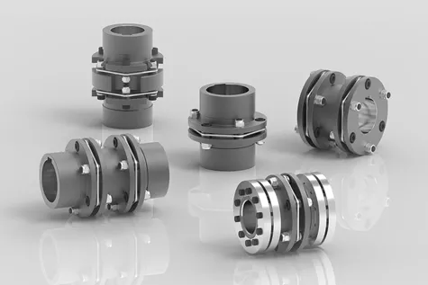
Common Applications of Disc Couplings
Disc couplings find extensive use across various industries and applications where reliable torque transmission, misalignment compensation, and torsional stiffness are essential. Some notable examples include:
- Industrial Machinery: Disc couplings are employed in industrial equipment such as pumps, compressors, generators, and conveyors. They ensure precise torque transfer and alignment in heavy-duty machinery.
- Power Generation: Gas turbines, steam turbines, and power generators often utilize disc couplings to transmit torque between components while withstanding high rotational speeds.
- Aerospace: In aircraft and spacecraft, disc couplings help connect critical systems like engines and auxiliary power units, ensuring dependable torque transmission in demanding environments.
- Marine: Ships and offshore platforms use disc couplings to connect propulsion systems, generators, and other machinery, even in conditions with variable loads and misalignments.
- Oil and Gas: Disc couplings play a crucial role in drilling rigs, pumps, and other equipment where reliable torque transmission and misalignment compensation are vital.
- Automotive: Some automotive applications use disc couplings to connect components within drivetrains and transmissions, especially in vehicles with high-performance requirements.
These examples highlight the versatility and importance of disc couplings in various industries where precise torque transmission, misalignment handling, and torsional stiffness are critical for optimal performance.
Diagnosing and Troubleshooting Issues with Disc Couplings
Proper diagnosis and troubleshooting are essential to maintain the optimal performance of disc couplings within machinery systems. Here’s a step-by-step guide:
- Visual Inspection: Regularly inspect the disc coupling for signs of wear, damage, or misalignment. Look for disc fractures, corrosion, or unusual wear patterns.
- Noise and Vibration Analysis: Abnormal noise or excessive vibration could indicate misalignment, wear, or imbalance. Use vibration analysis tools to identify the source and severity of the issue.
- Torque and Load Monitoring: Monitor torque and load variations to detect abnormal fluctuations. Sudden changes could indicate issues with the coupling or connected components.
- Alignment Check: Verify that the coupling and shafts are properly aligned. Misalignment can lead to premature wear and reduced coupling performance.
- Temperature Analysis: Monitor the operating temperature of the coupling. Excessive heat can result from friction due to misalignment or insufficient lubrication.
- Lubrication Inspection: Ensure proper lubrication between the disc elements and hubs. Inadequate lubrication can lead to increased wear and reduced flexibility.
- Dynamic Testing: Perform dynamic tests to evaluate the coupling’s response to torque fluctuations and misalignment. Analyze the results for anomalies.
- Replacement of Worn Parts: If wear or damage is detected, replace worn disc elements, hubs, or other components as needed.
- Rebalancing: If vibration is an issue, consider rebalancing the connected components to reduce vibration and enhance overall system stability.
Regular monitoring and a proactive approach to addressing issues can help prevent costly downtime and ensure the longevity of the disc coupling and the machinery system as a whole.
Considerations for Selecting a Disc Coupling for a Specific Application
Choosing the right disc coupling for a particular application involves considering several important factors to ensure optimal performance and reliability:
- Torque Requirements: Determine the maximum and continuous torque requirements of the application. Select a disc coupling that can handle the expected torque without exceeding its rated capacity.
- Misalignment: Evaluate the type and magnitude of misalignment expected in the system, including angular, parallel, and axial misalignment. Choose a disc coupling with the appropriate misalignment capability to accommodate these factors.
- Speed and RPM: Consider the operating speed and rotational speed of the connected shafts. High-speed applications may require disc couplings with balanced design to prevent vibration issues.
- Space Limitations: Evaluate the available space for installing the coupling. Disc couplings are compact and can be suitable for applications with limited space.
- Environmental Conditions: Assess the operating environment, including temperature, humidity, presence of corrosive agents, and exposure to dust or debris. Choose materials and coatings that can withstand the environmental conditions.
- Shaft Sizes: Ensure that the disc coupling’s hub bore sizes match the shaft sizes of the connected equipment.
- Alignment Maintenance: Consider the ease of installation and alignment maintenance. Some disc couplings feature spacer elements that simplify alignment and reduce downtime during maintenance.
- Backlash: Evaluate the backlash or play that the coupling introduces between the shafts. Backlash can affect the accuracy of position and torque transmission in precision applications.
- Dynamic Balancing: For high-speed applications, consider disc couplings that are dynamically balanced to prevent vibration issues that can arise from rotational imbalance.
- Resonance and Damping: Determine if the coupling design includes features to dampen vibrations and reduce the risk of resonance in the system.
- Service Life: Estimate the expected service life based on the application’s duty cycle and requirements. Choose a disc coupling with a suitable service life to avoid frequent replacements.
- Cost and Value: Compare the cost of the disc coupling with its features, performance benefits, and expected lifespan. Choose a coupling that provides the best value for your specific application.
By carefully considering these factors, you can select a disc coupling that meets the unique requirements of your machinery system and ensures reliable operation.


editor by CX 2024-04-29