Product Description
Drive Pipe Spline Shaft Disc Flange Gear Rubber Jaw Motor Spacer Beam Rigid Fluid Chain Nm Mh HRC Pin Fenaflex Spacer Elastomeric Flexible Gear Coupling
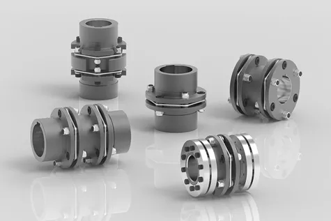
Main products
Coupling refers to a device that connects 2 shafts or shafts and rotating parts, rotates together during the transmission of motion and power, and does not disengage under normal conditions. Sometimes it is also used as a safety device to prevent the connected parts from bearing excessive load, which plays the role of overload protection.
Couplings can be divided into rigid couplings and flexible couplings.
Rigid couplings do not have buffering property and the ability to compensate the relative displacement of 2 axes. It is required that the 2 axes be strictly aligned. However, such couplings are simple in structure, low in manufacturing cost, convenient in assembly and disassembly, and maintenance, which can ensure that the 2 axes are relatively neutral, have large transmission torque, and are widely used. Commonly used are flange coupling, sleeve coupling and jacket coupling.
Flexible coupling can also be divided into flexible coupling without elastic element and flexible coupling with elastic element. The former type only has the ability to compensate the relative displacement of 2 axes, but cannot cushion and reduce vibration. Common types include slider coupling, gear coupling, universal coupling and chain coupling; The latter type contains elastic elements. In addition to the ability to compensate the relative displacement of 2 axes, it also has the functions of buffering and vibration reduction. However, due to the strength of elastic elements, the transmitted torque is generally inferior to that of flexible couplings without elastic elements. Common types include elastic sleeve pin couplings, elastic pin couplings, quincunx couplings, tire type couplings, serpentine spring couplings, spring couplings, etc
Company Profile
Our Factory
Application – Photos from our partner customers
/* January 22, 2571 19:08:37 */!function(){function s(e,r){var a,o={};try{e&&e.split(“,”).forEach(function(e,t){e&&(a=e.match(/(.*?):(.*)$/))&&1
Indicators of Wear or Damage in Disc Couplings
Disc couplings can exhibit signs of wear or damage over time due to factors like misalignment, overloading, or general usage. Detecting these issues early is crucial for preventing further damage. Some common indicators of wear or damage in disc couplings include:
- Vibration: Excessive vibration during operation can signal misalignment, component wear, or imbalance in the disc coupling.
- Noise: Unusual noises like clicking, clanking, or rattling can indicate wear, misalignment, or damage in the coupling components.
- Heat Generation: Excessive heat near the coupling area can suggest friction or misalignment issues.
- Reduced Performance: Decreased efficiency, torque transmission, or system performance may point to coupling wear or damage.
- Visual Inspection: Look for signs of visible wear, corrosion, cracks, or deformation on the coupling components.
To detect these signs of wear or damage, regular visual inspections, vibration analysis, and performance monitoring are essential. Early detection allows for timely maintenance or replacement of the affected components, ensuring the continued reliability and safety of the disc coupling and the machinery it serves.
Diagnosing and Troubleshooting Issues with Disc Couplings
Proper diagnosis and troubleshooting are essential to maintain the optimal performance of disc couplings within machinery systems. Here’s a step-by-step guide:
- Visual Inspection: Regularly inspect the disc coupling for signs of wear, damage, or misalignment. Look for disc fractures, corrosion, or unusual wear patterns.
- Noise and Vibration Analysis: Abnormal noise or excessive vibration could indicate misalignment, wear, or imbalance. Use vibration analysis tools to identify the source and severity of the issue.
- Torque and Load Monitoring: Monitor torque and load variations to detect abnormal fluctuations. Sudden changes could indicate issues with the coupling or connected components.
- Alignment Check: Verify that the coupling and shafts are properly aligned. Misalignment can lead to premature wear and reduced coupling performance.
- Temperature Analysis: Monitor the operating temperature of the coupling. Excessive heat can result from friction due to misalignment or insufficient lubrication.
- Lubrication Inspection: Ensure proper lubrication between the disc elements and hubs. Inadequate lubrication can lead to increased wear and reduced flexibility.
- Dynamic Testing: Perform dynamic tests to evaluate the coupling’s response to torque fluctuations and misalignment. Analyze the results for anomalies.
- Replacement of Worn Parts: If wear or damage is detected, replace worn disc elements, hubs, or other components as needed.
- Rebalancing: If vibration is an issue, consider rebalancing the connected components to reduce vibration and enhance overall system stability.
Regular monitoring and a proactive approach to addressing issues can help prevent costly downtime and ensure the longevity of the disc coupling and the machinery system as a whole.
Function of Disc Couplings in Torque Transmission and Misalignment Compensation
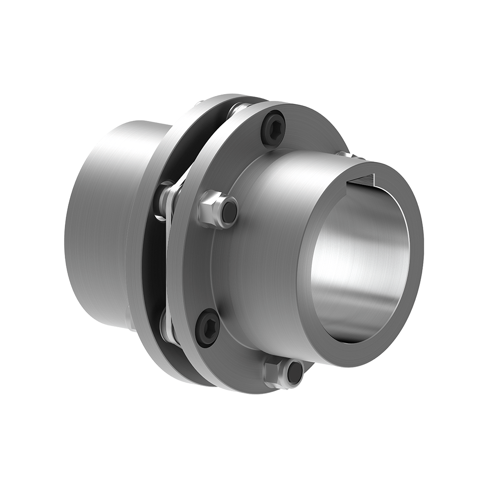
Disc couplings are designed to transmit torque between two shafts while accommodating various forms of misalignment. The primary components of a disc coupling include two hubs and a flexible disc element made of a resilient material such as stainless steel. Here’s how a disc coupling works to transmit torque and handle misalignment:
- Torque Transmission: When torque is applied to one hub of the disc coupling, it induces angular displacement in the flexible disc. The flexible disc element bends slightly, allowing the torque to be transmitted from one hub to the other. This bending action of the disc results in an elastic deformation, which helps maintain the torque transfer.
- Angular Misalignment Compensation: Disc couplings can accommodate angular misalignment between the two connected shafts. As the hubs are misaligned angularly, the flexible disc element compensates by bending at an angle. The disc’s flexibility and the elastic properties of the material allow it to absorb and accommodate the angular misalignment without transmitting excessive forces to the connected machinery.
- Parallel Misalignment Compensation: In cases of parallel misalignment, where the axes of the two shafts are not perfectly aligned, the disc coupling can also absorb a certain degree of parallel offset. The flexibility of the disc allows for slight axial movement, ensuring that the hubs remain connected even when there’s a minor parallel misalignment.
- Torsional Stiffness: While disc couplings are designed to accommodate misalignment, they also exhibit torsional stiffness. This means that under normal operating conditions, the disc coupling remains rigid enough to efficiently transmit torque between the shafts, minimizing torsional deflection and maintaining the integrity of torque transfer.
The design and material properties of the flexible disc element play a crucial role in determining the coupling’s ability to handle misalignment while transmitting torque effectively. Disc couplings are widely used in various industrial applications where torque transmission and misalignment compensation are critical requirements.


editor by CX 2024-05-06